A very inexpensive way to establish a wireless connection are these cheap China 433 MHz transmitter-receiver units. You can get a pair for less than $2 online and they can have a range higher than 100 m. For easy hook up to the Arduino, there is also the Virtual Wire library. However I decided not to use the wireless library, because of two reasons: I wanted to figure it out and I wanted to know what it does for the case it doesn’t work perfectly.
Since it seemed a bit tricky to me how they worked and I ended up needing an oscilloscope to understand, what was going on, I will write this down here.
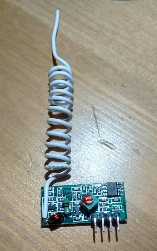
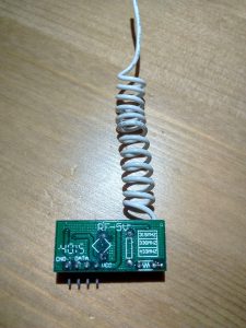
The module has 4 Pins: GND, 2x DATA and VCC. Both data pins seem to be connected.
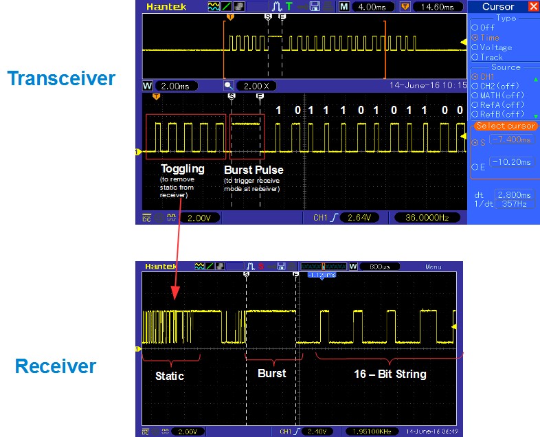
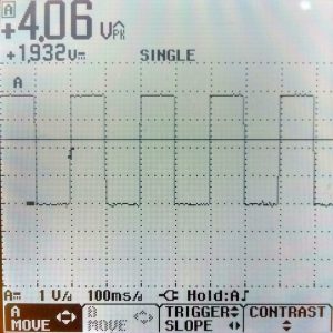
One thing I can say beforehand, I did not calculate with the static of these modules. After experimenting for a bit, I found that there must be static, however I needed an oscilloscope to really understand the nature of the static. Receiver Signal reading a 0.1 Hz Signal (rectangle) from the Transceiver. About 400 ms after the rising edge, the static becomes dominating.
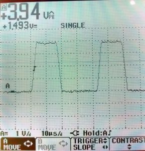
The oscilloscope snapshot above shows a 0.1 Hz signal at the data pin on the receiver. The voltage is pretty much at 4 V, however static happens at both, logic low and logic high level. Obviously, the signal has to move a lot faster to avoid static. With 5 Hz, it looks already very different: Receiver Signal with 5 Hz. At this frequency, the static is gone and the duty cycle is almost exactly 50%. With 5 Hz it looks very good, the static was already gone at 1.5 Hz, however the low and high side of the signal was not balanced, or in other words, the duty cycle was off. I tried this up to frequencies of 25 kHz, then the signal became distorted again: Receiver Signal at 25 kHz. The edges show a significantly slower slew rate. However I cannot say for 100%, if this was caused by the oscilloscope I used. Since I found that signals up to 25 kHz are received very clean without static and that the voltage level of the Data line is ~4 V, I decided to use the digital inputs of the AVR. This is possible, because the AVR inputs interpret voltages lower than 2.2 V as LOW and higher than 2.6 V as HIGH (0.4 V of hysteresis).
What I found out was, that the receiver will always show static, when the sender doesn’t send of sends for too long. With too long I mean more than 300 ms. That means, despite of the 433 MHz carrier frequency, the receiver will read static, if the transceiver didn’t switch the logic level for more than 300 ms. I don’t know, what would happen with analog commands to the transceiver, since the AVRs don’t have any analog outputs.
Furthermore I decided to use frequency modulation to for the data transfer and the pin change interrupt at the receiver, to decode the frequency at the receiver. Also found that it is helpful to start the transfer with some signal toggling, to remove the static from the sender module, followed by a burst signal with a certain period length to trigger the reception: